Animated Beam
A deep dive into SVG coordinate calculations, quadratic Bezier curves, dynamic ResizeObservers, and Framer Motion linear gradients.
Implementation breakdown of the Animated Beam component, covering its layout-relative positioning, quadratic Bezier calculations, and Framer Motion keyframe gradient animation.
[!NOTE] This component is referenced from the Magic UI Animated Beam.
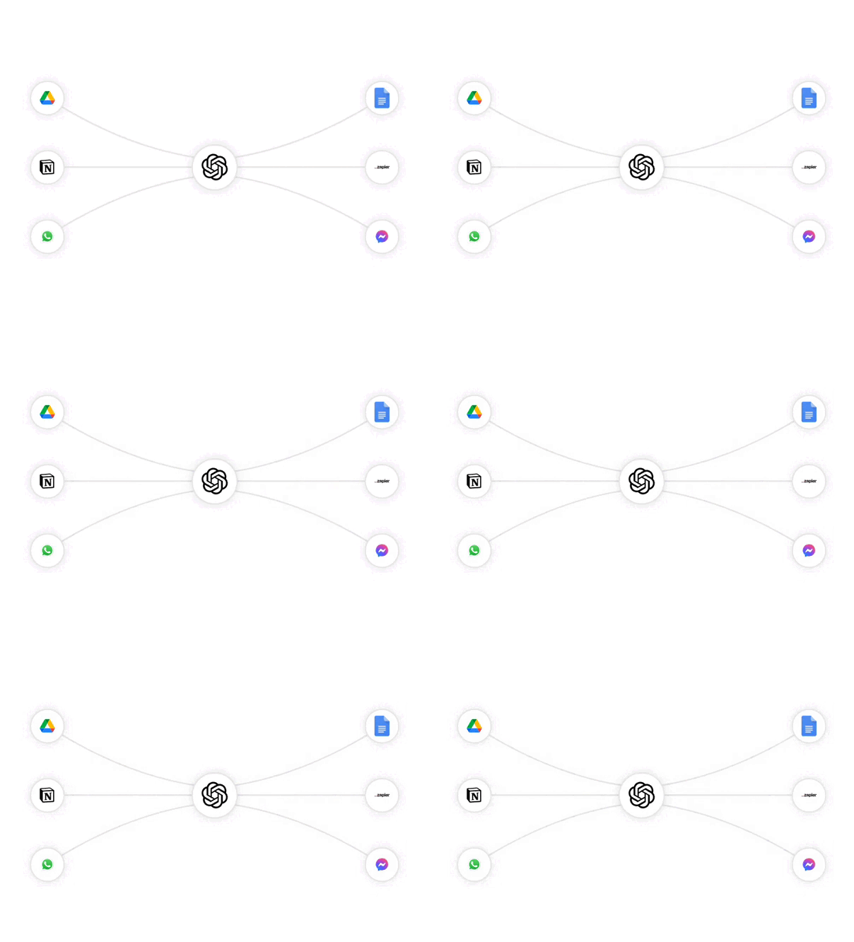
1. High-Level Flow Chart
The following diagram illustrates how the AnimatedBeam component tracks element positions, constructs a curve in local container space, and applies a moving linear gradient to animate the beam:
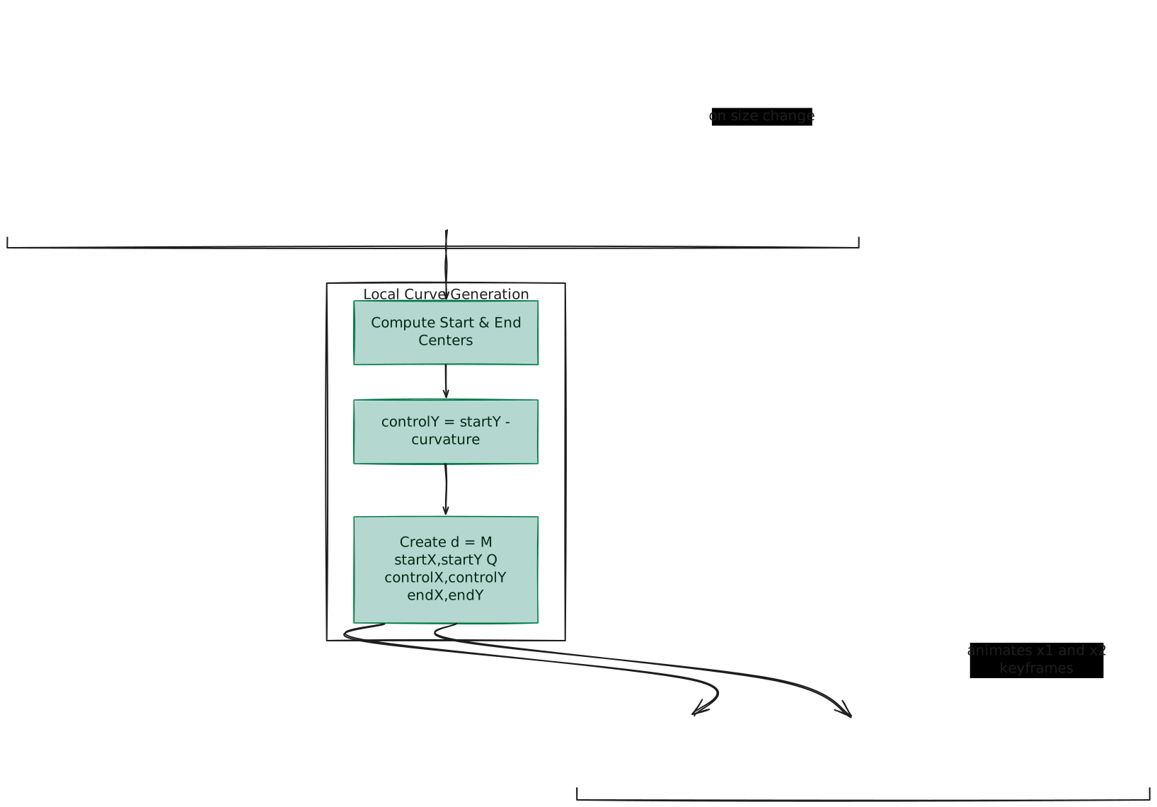
2. Component Implementation (animated-beam.tsx)
Below is the complete implementation of the AnimatedBeam component using React and Framer Motion:
"use client"

import { useEffect, useId, useState, type RefObject } from "react"
import { motion } from "motion/react"

import { cn } from "@/lib/utils"

export interface AnimatedBeamProps {
  className?: string
  containerRef: RefObject<HTMLElement | null> // Container ref
  fromRef: RefObject<HTMLElement | null>
  toRef: RefObject<HTMLElement | null>
  curvature?: number
  reverse?: boolean
  pathColor?: string
  pathWidth?: number
  pathOpacity?: number
  gradientStartColor?: string
  gradientStopColor?: string
  delay?: number
  duration?: number
  repeat?: number
  repeatDelay?: number
  startXOffset?: number
  startYOffset?: number
  endXOffset?: number
  endYOffset?: number
}

export const AnimatedBeam: React.FC<AnimatedBeamProps> = ({
  className,
  containerRef,
  fromRef,
  toRef,
  curvature = 0,
  reverse = false, // Include the reverse prop
  duration = 5,
  delay = 0,
  pathColor = "gray",
  pathWidth = 2,
  pathOpacity = 0.2,
  gradientStartColor = "#ffaa40",
  gradientStopColor = "#9c40ff",
  repeat = Infinity,
  repeatDelay = 0,
  startXOffset = 0,
  startYOffset = 0,
  endXOffset = 0,
  endYOffset = 0,
}) => {
  const id = useId()
  const [pathD, setPathD] = useState("")
  const [svgDimensions, setSvgDimensions] = useState({ width: 0, height: 0 })

  // Calculate the gradient coordinates based on the reverse prop
  const gradientCoordinates = reverse
    ? {
      x1: ["90%", "-10%"],
      x2: ["100%", "0%"],
      y1: ["0%", "0%"],
      y2: ["0%", "0%"],
    }
    : {
      x1: ["10%", "110%"],
      x2: ["0%", "100%"],
      y1: ["0%", "0%"],
      y2: ["0%", "0%"],
    }

  useEffect(() => {
    const updatePath = () => {
      if (containerRef.current && fromRef.current && toRef.current) {
        const containerRect = containerRef.current.getBoundingClientRect()
        const rectA = fromRef.current.getBoundingClientRect()
        const rectB = toRef.current.getBoundingClientRect()

        const svgWidth = containerRect.width
        const svgHeight = containerRect.height
        setSvgDimensions({ width: svgWidth, height: svgHeight })

        const startX =
          rectA.left - containerRect.left + rectA.width / 2 + startXOffset
        const startY =
          rectA.top - containerRect.top + rectA.height / 2 + startYOffset
        const endX =
          rectB.left - containerRect.left + rectB.width / 2 + endXOffset
        const endY =
          rectB.top - containerRect.top + rectB.height / 2 + endYOffset

        const controlY = startY - curvature
        const d = `M ${startX},${startY} Q ${(startX + endX) / 2
          },${controlY} ${endX},${endY}`
        setPathD(d)
      }
    }

    // Initialize ResizeObserver
    const resizeObserver = new ResizeObserver(() => {
      updatePath()
    })

    // Observe the container element
    if (containerRef.current) {
      resizeObserver.observe(containerRef.current)
    }

    // Call the updatePath initially to set the initial path
    updatePath()

    // Clean up the observer on component unmount
    return () => {
      resizeObserver.disconnect()
    }
  }, [
    containerRef,
    fromRef,
    toRef,
    curvature,
    startXOffset,
    startYOffset,
    endXOffset,
    endYOffset,
  ])

  return (
    <svg
      fill="none"
      width={svgDimensions.width}
      height={svgDimensions.height}
      xmlns="http://www.w3.org/2000/svg"
      className={cn(
        "pointer-events-none absolute top-0 left-0 transform-gpu stroke-2",
        className
      )}
      viewBox={`0 0 ${svgDimensions.width} ${svgDimensions.height}`}
    >
      <path
        d={pathD}
        stroke={pathColor}
        strokeWidth={pathWidth}
        strokeOpacity={pathOpacity}
        strokeLinecap="round"
      />
      <path
        d={pathD}
        strokeWidth={pathWidth}
        stroke={`url(#${id})`}
        strokeOpacity="1"
        strokeLinecap="round"
      />
      <defs>
        <motion.linearGradient
          className="transform-gpu"
          id={id}
          gradientUnits={"userSpaceOnUse"}
          animate={{
            x1: gradientCoordinates.x1,
            x2: gradientCoordinates.x2,
            y1: gradientCoordinates.y1,
            y2: gradientCoordinates.y2,
          }}
          transition={{
            delay,
            duration,
            ease: [0.16, 1, 0.3, 1], // https://easings.net/#easeOutExpo
            repeat,
            repeatDelay,
          }}
        >
          <stop stopColor={gradientStartColor} stopOpacity="0"></stop>
          <stop stopColor={gradientStartColor}></stop>
          <stop offset="32.5%" stopColor={gradientStopColor}></stop>
          <stop
            offset="100%"
            stopColor={gradientStopColor}
            stopOpacity="0"
          ></stop>
        </motion.linearGradient>
      </defs>
    </svg>
  )
}
3. Position Calculation & Relative Coordinates
To draw a line from Node A to Node B, the component needs to map coordinates dynamically relative to the parent container.
A. Viewport to Content Coordinates Calculation
Standard layout boundaries are calculated in browser global space via getBoundingClientRect().
To represent coordinates inside the SVG canvas (where (0, 0) sits exactly at the container's top-left corner), the container's screen offset must be subtracted from the node's screen offset:
-
startX = (rectA.left - containerRect.left) + (rectA.width / 2) + startXOffset -
startY = (rectA.top - containerRect.top) + (rectA.height / 2) + startYOffset -
endX = (rectB.left - containerRect.left) + (rectB.width / 2) + endXOffset -
endY = (rectB.top - containerRect.top) + (rectB.height / 2) + endYOffset -
Subtraction (
rectA.left - containerRect.left): Shifts coordinates from viewport-relative to container-relative. -
Midpoint Center Offset (
+ rectA.width / 2): Shifts the point from the element's top-left corner to its geometric center. -
Dynamic Offset Adjustments (
+ startXOffset): Allows fine-tuning of the start and end connection coordinates. Developers can shift coordinates relative to the node’s center to prevent target overlaps when rendering multiple lines connecting to or from the same elements.
B. Dynamically Resizing SVG Boundaries
If we were to position the <svg> component using standard CSS constraints such as inset-0 with no explicit pixel dimensions:
- The browser defaults to setting the SVG canvas size to
300px * 150px. - Stretching this region using CSS triggers coordinate stretching (the Rubber Band Effect). This distorts the stroke-width rendering (adding blurriness) and breaks coordinate mapping alignment.
To preserve a 1:1 pixel coordinate mapping without stretching:
- The viewport size tracking state (
svgDimensions) measures client width and height dynamically. - The component sets explicit SVG properties: width mapping to
svgDimensions.width, height mapping tosvgDimensions.height, and viewBox matching"0 0 width height". - A
ResizeObservermonitors the parent container, invoking dimensions updates immediately on resize. This shifts connection nodes response points and updates the Bezier curve coordinates instantly.
4. Quadratic Bezier Curve Mathematics
The connection line curves smoothly using SVG's Quadratic Bezier Curve (Q command) inside the d data string:
Start Point (startX, startY) ─► Control Point (controlX, controlY) ─► End Point (endX, endY)The data format command is structured as follows:
d = "M startX,startY Q controlX,controlY endX,endY"
A. The Control Point Magnet
The Control Point acts as a virtual magnet pulling the path toward it.
- Horizontal Balance (
controlX): Positioned exactly at the midpoint:(startX + endX) / 2. This keeps the bend symmetrical and centered. - Vertical Curve Height (
controlY = startY - curvature): Controls the amount of arch.
In the web's coordinate space, Y increases downwards (top-left is (0, 0)):
- Positive Curvature (
curvature = 50): Decreases Y (startY - 50), pulling the control point up, creating an upward arch. - Negative Curvature (
curvature = -50): Increases Y (startY + 50), pulling the control point down, creating a hanging sag.
(0,0) Container Top-Left
 ┌───────────────────────────────────────────────┐
 │                   [Control Point]             │ (Height = startY - curvature)
 │                       .  •  .                 │
 │                    .           .              │
 │          (Start) 🔘             🔘 (End)      │ (Height = startY)
└───────────────────────────────────────────────┘- Zero Curvature (
curvature = 0): The control point sits exactly on the horizontal starting baseline. If the start and end nodes are at different heights, the curve starts horizontal and then drops down to the destination (yielding a custom diagonal curve rather than a straight line).
B. The 50% Principle of Bezier Curves
A quadratic Bezier curve is attracted to the control point (which acts like a virtual magnet) but mathematically never reaches it. Instead, the center peak of the curve always bends to sit exactly halfway between the straight line connecting the two nodes (the straight midpoint) and the control point (the magnet):
Curve Midpoint = 0.5 * (Straight Midpoint) + 0.5 * (Control Point)
For example, if the straight line between two nodes sits at height 100px, and the control point is pulled up to height 20px, the peak of the curve will sit exactly halfway between them at height 60px.
5. Dual-Path Layering & Gradient Physics
The glowing beam animation is an optical illusion generated by rendering two overlapping paths with identical geometries. They share the exact same curve coordinates (d={pathD}) and dimensions, resulting in a perfect 1:1 spatial overlap where one sits directly on top of the other.
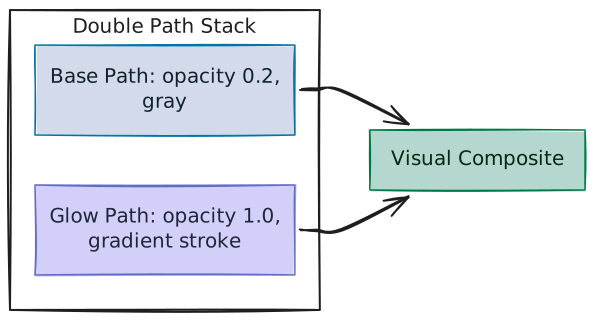
- Background Track: The first
<path>uses standard coloring (strokeWidth,opacity="0.2") to render a static, faint connection guide. - Glow Track: The second
<path>mounts directly on top, using the ID pointer of a<linearGradient>as its stroke texture:stroke="url(#id)".
- Visual Composite: The final rendered output. Stacking the glow overlay directly over the static base path merges them: fully opaque gradient segments hide the base line, while transparent segments let the faint background path (at 20% opacity) show through to create the pulse-on-a-wire effect.
A. The Horizontal Scanner Bar Analogy
The animation sweeps coordinates horizontally:
x1keyframes:["10%", "110%"]or["90%", "-10%"](reverse)x2keyframes:["0%", "100%"]or["100%", "0%"](reverse)y1/y2keyframes:["0%", "0%"]
Since y1 and y2 are locked to 0%, the linear gradient behaves like a perfectly vertical scanner bar sliding left to right.
Even though the connection curve stretches up and down, the curve still progresses left to right. The vertical scanner bar illuminates the curve segment-by-segment as it passes through, meaning we do not need to calculate dynamic Y coordinates along the curve!
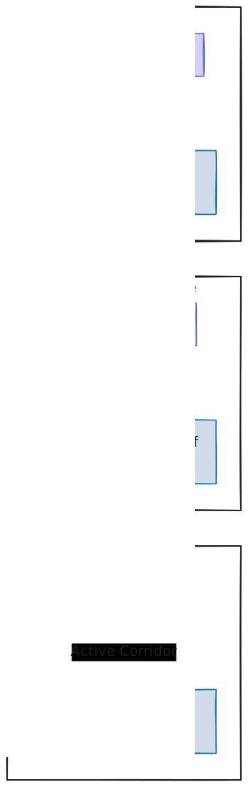
B. Gradient Stops and Padding
To contain the glowing pulse within a specific length, we configure the gradient <stop> offsets:
| Offset | Opacity | Description |
|---|---|---|
0% | 0 | Keeps the glow path behind the moving pulse completely transparent (revealing only the static background path). |
0% | 1 | Creates a sharp, solid start edge for the glow. |
32.5% | 1 | The solid color transition window (Color A to Color B). |
100% | 0 | Gradual alpha decay, shaping the soft "comet tail" fadeout. |
In SVG, if a path extends outside the linear gradient's bounds, the browser repeats the edge colors infinitely (configured by spreadMethod="pad").
- By adding a transparent stop at
0%(Stop 1) and a transparent stop at100%(Stop 4), the browser pads all coordinates outside the active corridor with transparency. This keeps the rest of the glow path transparent (so only the static background path is visible) and allows the pulse to loop seamlessly without clips. - The
10%difference betweenx1andx2limits the active corridor to exactly10%of the parent's layout width.
6. Advanced Settings & Property Reference
Key Rendering Configurations
gradientUnits="userSpaceOnUse": Sets the gradient's coordinate space mapping to the parent SVG canvas instead of the path's bounding box (objectBoundingBox). This ensures that the percentage sweeps map to the container dimensions rather than scaling down to the size of the single path.- Instances Safety via
useId: Generates a unique component ID dynamically. If multiple beams render on the same page, they use independent gradient definitions, preventing rendering conflicts or visual overlaps.
Customizable Properties Reference
| Property | Default | Type | Description |
|---|---|---|---|
containerRef | Required | RefObject | Reference pointer to the parent layout wrapper. |
fromRef | Required | RefObject | Reference pointer to the starting connector node. |
toRef | Required | RefObject | Reference pointer to the ending connector node. |
curvature | 0 | number | Curve arch distance in pixels. |
reverse | false | boolean | Reverses the beam direction (reverse moves right-to-left). |
duration | 5 | number | Travel speed duration in seconds. |
delay | 0 | number | Timing offset delay before the animation loops. |
pathColor | "gray" | string | Base connection path stroke color. |
pathWidth | 2 | number | Base and glow lines stroke thickness. |
pathOpacity | 0.2 | number | Opacity scale of the background connection line. |
gradientStartColor | "#ffaa40" | string | Starter glow color of the linear gradient. |
gradientStopColor | "#9c40ff" | string | Ending glow color of the linear gradient. |
startXOffset | 0 | number | Horizontal starting offset adjustment in pixels. |
startYOffset | 0 | number | Vertical starting offset adjustment in pixels. |
endXOffset | 0 | number | Horizontal ending offset adjustment in pixels. |
endYOffset | 0 | number | Vertical ending offset adjustment in pixels. |