The OSI Model
An overview of the OSI model, its 7 layers, and why it matters in system design.
To design scalable systems, we must first understand how computers talk to each other across a network. Whether a browser is fetching a webpage, or a microservice is querying a database, data has to travel from one machine to another.
To make sense of this complex process, we use the OSI Model.
What is the OSI Model?
The OSI (Open Systems Interconnection) Model is a conceptual framework that standardizes how different computer systems communicate over a network. It breaks down the network communication process into 7 distinct layers.
[!NOTE] Conceptual vs. Reality: The modern internet does not strictly implement the 7-layer OSI model; instead, it runs on a simpler model called the TCP/IP model (commonly mapped as 4 or 5 layers). However, we still use the OSI model's terminology (like "Layer 4" or "Layer 7") as a universal shorthand to describe where different networking technologies operate.
Why Should We Care?
As developers, we rarely need to worry about physical cables or signal frequencies. However, we absolutely need to understand:
- How data is formatted and secured (e.g., HTTPS encryption).
- How connection reliability is managed (e.g., choosing between TCP and UDP).
- How traffic is routed (e.g., Layer 4 vs. Layer 7 Load Balancing).
Understanding the layers helps us debug connectivity issues, write network-efficient code, and make informed architectural decisions.
The 7 Layers (Top-Down Approach)
Since we write applications that live at the top layer and send data downwards, we will explore the model from Layer 7 down to Layer 1.
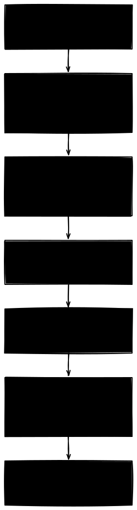
7. The Application Layer (Layer 7)
This is the entry point where our software applications interact with the network. When we make a web request, load a page, or call an API, the network journey starts here at this layer.
- Protocols: HTTP, HTTPS, WebSockets, DNS, SMTP (Email), SSH.
- Our Perspective: When we call
fetch("https://api.example.com/users"), our code only deals with Layer 7 concepts (like HTTP methods, headers, and URL paths). The browser or runtime environment automatically handles and abstracts away the lower layers (like establishing TCP connections or routing packets) for us.
6. The Presentation Layer (Layer 6)
This layer acts as the translator for the network. It ensures that the data sent from the application layer of one system is readable by the application layer of another. It handles:
- Translation & Formatting: Converting raw application data into a standard format (like serializing objects to JSON/XML).
- Encryption & Decryption: This is where TLS/SSL encryption happens, securing our HTTPS traffic.
- Compression: Reducing data size to speed up transmission.
- Our Perspective: When we parse JSON in our code, or when the browser/runtime automatically encrypts and decrypts our traffic during an HTTPS request, this relies on Presentation Layer logic to format and secure the data.
[!NOTE] TLS & Secure Connections When we connect to an
https://site, the browser or runtime negotiates a secure connection using TLS (Transport Layer Security) before sending any data. This TLS handshake performs key exchange and encrypts data at the Presentation Layer.Since this process requires extra network round-trips (adding startup latency), we use connection pooling to reuse active connections.
We will explore the exact mechanics of TLS handshakes, asymmetric vs. symmetric cryptography, and SSL certificates in detail in our upcoming Security & Authentication post.
5. The Session Layer (Layer 5)
This layer is responsible for opening, managing, and closing communication channels (sessions) between two devices. It ensures that sessions remain open long enough to transfer all data, and closes them promptly to avoid wasting resources.
- Key Functions: Session checkpointing, session synchronization, and connection state management.
- Our Perspective: A classic example is a Database Connection Session (like connecting to PostgreSQL or MySQL). Unlike web browsers communicating over HTTP, databases connect over their own custom binary protocols directly on top of TCP. When our backend database client library initiates a connection, the database server spawns a dedicated process or thread to manage that specific connection session. The database engine authenticates the connection, tracks our transaction state, stores session-level settings (like timezones or temporary tables), and monitors connection health. When the client library closes the connection, the database tears down the session and frees up resources.
4. The Transport Layer (Layer 4)
The transport layer coordinates the transfer of data between host systems. It takes data from the session layer and breaks it into smaller pieces called segments (or reconstructs segments back into data on the receiving end).
- Key Protocols:
- TCP (Transmission Control Protocol): Connection-oriented. It guarantees that all segments arrive in order and without errors by using acknowledgments and retransmitting lost packets.
- UDP (User Datagram Protocol): Connectionless. It sends data immediately without verifying if it was received. It is much faster but does not guarantee delivery.
- Our Perspective: This is where we choose the transport protocol (via our application's network configurations or library choices) depending on whether our service needs reliability (TCP, e.g., for REST APIs, database connections) or speed (UDP, e.g., for live multiplayer gaming, real-time video streaming).
Deep Dive: The TCP 3-Way Handshake
To guarantee reliability, TCP requires a connection to be established before any data can flow. This is done via the 3-way handshake:
- SYN (Synchronize): The client sends a request to open a connection with an initial sequence number.
- SYN-ACK (Synchronize-Acknowledgment): The server acknowledges the request and sends back its own sequence number.
- ACK (Acknowledge): The client acknowledges the server's response, establishing the connection.
Why this matters to us: Establishing a new TCP connection requires a full 1 RTT (Round-Trip Time) of handshake latency—the time it takes for a data packet to travel to the server and back—before any application data can be sent. To avoid paying this startup penalty on every request, we configure Connection Pools in our application code to reuse established connections.
[!NOTE] We will explore transport-layer mechanics (like TCP vs. UDP differences, flow control, congestion windowing, and HTTP/3 migrating to UDP/QUIC) in a dedicated Transport Protocols & HTTP Evolution post.
3. The Network Layer (Layer 3)
The network layer is responsible for moving data between different networks. It handles routing (finding the best physical path for the data) and logical addressing.
- Data Unit: Packets.
- Key Concepts: IP Addresses (IPv4, IPv6), Routers.
- Our Perspective: When we assign an IP address to a virtual machine or configure routing tables in AWS (VPC routing), we are configuring Layer 3.
2. The Data Link Layer (Layer 2)
While the Network Layer moves data between different networks, the Data Link Layer moves data between two devices on the same local network. It handles physical addressing and error detection on the local link.
- Data Unit: Frames.
- Key Concepts: MAC Addresses, Network Switches, Ethernet, Wi-Fi.
- Our Perspective: We don't interact with Layer 2 directly in our code. Instead, our physical devices (like our laptop's network card) and local switches use MAC addresses at Layer 2 to route data frames to the correct hardware device on the local network.
Deep Dive: IP Address vs. MAC Address (Why We Need Both)
A common point of confusion is why we need both IP addresses (Layer 3) and MAC addresses (Layer 2).
- IP Address (Logical Address): Think of this as a mailing address (e.g., 123 Main St, Seattle, WA). It tells the routers of the world roughly where we are located. It changes depending on which Wi-Fi network we connect to.
- MAC Address (Physical Address): Think of this as our fingerprint or Social Security Number. It is a unique hardware identifier burned into our device's network card at the factory. While physically permanent on the hardware, it can be overridden (spoofed) or randomized by our operating system for privacy.
How they work together (Sending a Packet):
- Logical Destination (IP): Our computer sets the destination IP address (Layer 3) to the target server's IP. This destination IP never changes during transit.
- Next Physical Hop (MAC): Our computer cannot send signals directly to a remote server. It can only talk to the local router. So, it uses ARP to find the router's MAC address (Layer 2) and wraps the packet in a frame addressed to that MAC.
- Hop-by-Hop Routing: As the packet moves from router to router across the internet, the outer Layer 2 MAC header is stripped and rewritten at each hop to address the next physical machine.
- Final Delivery: Once the packet reaches the target network's router, it uses ARP to resolve the server's IP to its MAC address and delivers the final frame.
[!NOTE] How do routers know where to send? Every router in the internet chain maintains a Routing Table (a local directory):
- Fixed Subnets: IP addresses are grouped into fixed, static ranges (subnets) so routers don't have to store rules for billions of individual IPs.
- Dynamic Paths (Routing Gossip): While subnets are fixed, the physical paths to reach them are dynamic. Routers constantly "gossip" with their neighbors using routing protocols (like BGP or OSPF) to share which routes are active and fast. If a fiber cable breaks, they automatically recalculate and update their tables.
- The Relay Race: Multiple routers along the path all know how to forward packets to the same destination subnet. Each router looks up the packet's destination IP in its table and forwards it to the next physical hop in the chain.
- IP-to-MAC Mapping: To forward a packet, the router determines the next-hop IP from its Routing Table, and then looks up that IP's corresponding MAC address in its ARP Table to address the physical frame.
1. The Physical Layer (Layer 1)
The lowest layer represents the actual physical hardware that transmits raw bitstreams (0s and 1s) over a physical medium.
- Key Components: Fiber-optic cables, copper wires, radio waves (for wireless signals), network hubs, and connectors.
- Our Perspective: Even though we write high-level code, our software is still bound by physical limits. For example, if we deploy our application servers in Mumbai and our database in Delhi (separated by approximately 1,400 km), the network signal must travel through physical fiber-optic cables. Because of the speed of light in glass, this adds about 15ms of one-way network latency (resulting in a 30ms round-trip delay) to every database query. To keep our apps fast, we must deploy our servers and databases in the same physical data center region (like keeping both in Mumbai).
Data Flow: Encapsulation & Decapsulation
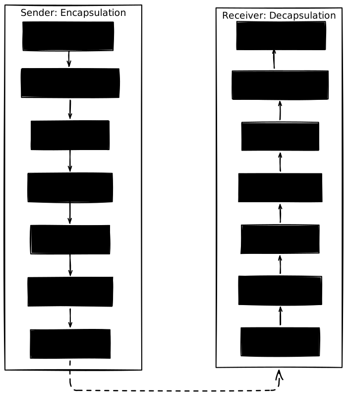
When we send a message, it doesn't just jump from our app to the recipient's app. It travels down the sender's stack and up the receiver's stack.
Encapsulation (Sending)
As data moves down from Layer 7 to Layer 1, each layer wraps the data with its own header containing metadata (like source and destination addresses, error-checking codes, etc.). This is like putting a letter inside an envelope, placing that envelope inside a shipping box, and sticking a routing label on the box.
Decapsulation (Receiving)
When the receiving device gets the physical bits, the data moves up from Layer 1 to Layer 7. Each layer strips off its corresponding header, processes the metadata, and passes the remaining payload up to the next layer.
[!NOTE] Performance Fact: OS kernels don't copy data to delete headers. They keep the packet in one buffer and simply move a pointer forward past each header as it gets processed.
Why This Matters in System Design
Understanding these layers is critical for making architectural decisions. Here are two classic system design scenarios where the OSI Model dictates our choices:
1. L4 vs. L7 Load Balancing
A load balancer distributes incoming network traffic across multiple servers based on different layers:
- Layer 4 (L4) Load Balancing: Operates at the Transport Layer. It routes traffic simply by looking at the IP and Port headers. Because it never decrypts the packets or reads the actual message content (like HTTP headers or URLs), it requires very little CPU and memory, allowing a single load balancer to handle massive throughput.
- Layer 7 (L7) Load Balancing: Operates at the Application Layer. It must decrypt the TLS/HTTPS connection and read the full HTTP request (headers, cookies, path) to make routing decisions (e.g., routing
/apito one service and/staticto another). This requires significantly more CPU for decryption and text parsing, but enables highly intelligent routing.
[!NOTE] How does L4 route? It hashes the client's source IP and port to select a backend, then rewrites the packet's destination IP to match that backend (via NAT) and forwards it immediately.
[!NOTE] We will explore load balancing algorithms, architectures, and implementation patterns in detail in the upcoming Load Balancing blog post.
2. Choosing a Transport Protocol (TCP vs. UDP)
When designing communication between services or clients, we must choose a protocol at Layer 4:
- Use TCP when accuracy is critical: For REST APIs, database queries, and file transfers, we cannot afford to lose a single packet. TCP guarantees that every byte is received.
- Use UDP when latency is critical: For real-time multiplayer games, voice-over-IP (VoIP), or live video streaming, speed is more important than a few dropped frames. If a video frame packet is lost, it is better to skip it and show the next frame rather than pausing the video to retransmit the old one.